Narda Safety Test Solutions Expands the Features of its Interference and Direction Analyzer
Pfullingen, Germany, July 1, 2015–Narda Safety Test Solutions has expanded the features of its Interference and Direction Analyzer: Spectrograms with a time resolution of as fine as 1 µs now allow insights into signal structures that were otherwise only possible with large scale lab equipment. This means that interference and hidden transmitters with rapidly changing frequencies can also be analyzed and then localized with subsequent operating steps.
 Because the available frequency spectrum is limited, many modern communications methods increasingly make use of frequency hopping (frequency hopping spread spectrum, FHSS): By changing frequency continuously, several devices can always find frequencies or channels that are unoccupied. Typical applications in the ISM frequency band include WLAN and Bluetooth, along with remote control for drones. Some GSM operating modes also use frequency hopping. Illegal transmitters make use of this method, too, hopping about to make themselves almost impossible to pinpoint. This type of interference can also occur unintentionally with transmitters operating legally. For example, if several mobile phone transmitters share the same transmitter location, the rectifying effect of just a couple of rusty rivets on the mast can generate in-band interference that is very difficult to distinguish from the wanted signals.
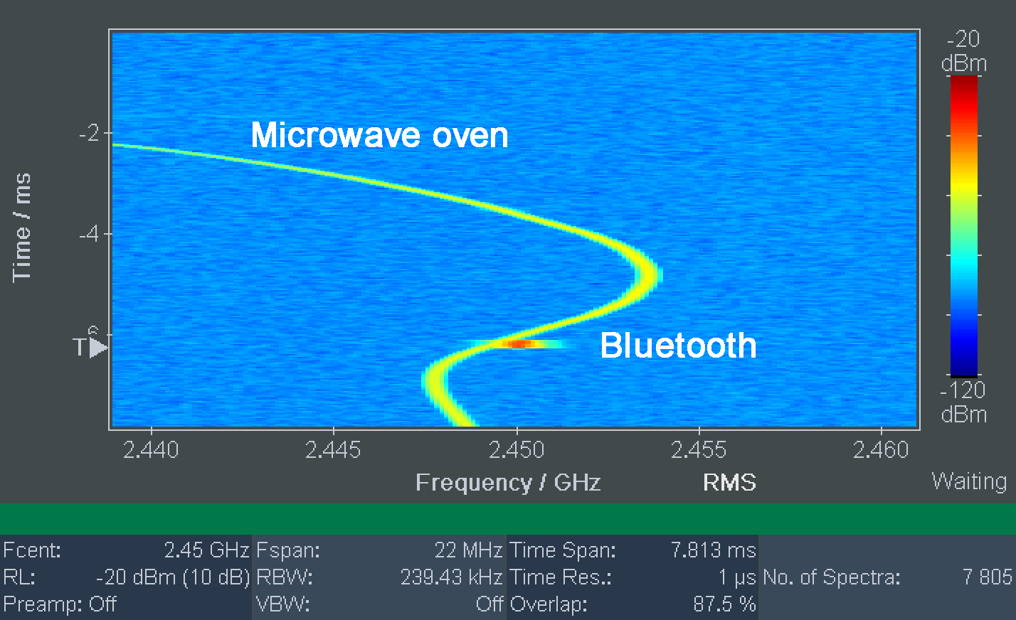
In the IDA 2’s new High Resolution Spectrogram display mode, the type of signal, i.e. its “fingerprint”, can be identified. The instrument writes the spectrums line by line, with levels indicated by different colors. In this way the time and spectral relationships can be seen immediately. With time resolution as fine as 1 µs, for example, LTE frame structures can be displayed, with any underlying dissimilar signals being immediately apparent because of their different frequency and time characteristics. The frequency and time signatures allow conclusions about the type of source to be drawn and mutual interference detected in multi use frequency ranges such as the ISM bands. The Magnitude display mode shows the level characteristic versus time and is useful for identifying signals using their time structures, for setting triggers, and lastly for locating their source.
Technical Background
The High Resolution Spectrogram and Magnitude display modes are based on the I/Q Analyzer operating mode. The IDA 2 operates with “zero span”, i.e. it is tuned to a fixed frequency or a particular channel, which it captures selectively and records the digitized data. A special feature of the instrument is the ability to set channel bandwidths (CBW) of up to 32 MHz.
For the High Resolution Spectrogram, the IDA 2 analyzes the data with a FFT using user definable parameters that can also be changed subsequently. For example: The FFT produces a usable bandwidth of 22 MHz for a channel bandwidth (CBW) of 32 MHz. With 256 FFT nodes, the IDA 2 computes a spectrum with a resolution bandwidth (RBW) of about 240 kHz. If a window overlap of 87.5 % is selected, the spectrums obtained will have a time resolution of 1 µs. In other words: one million spectrums per second. For this reason, conventional analyzers compress the data for resolutions finer than about 20 ms. IDA 2 is the first hand held device that retains the uncompressed data in the background and can display it with its original resolution as a Zoom: Every row of pixels corresponds exactly to one spectrum. The color corresponds to the particular level. The marker can be used to display each separate spectrum in the conventional way as level versus frequency.
IDA 2
The Interference and Direction Analyzer IDA 2 was designed to identify and localize the sources of electromagnetic signals. Its uses cover the fields of communications and security. For communications, it is important to locate and eliminate intrinsic or extrinsic interference. For security, the device can be used to trace unknown transmitters and identify potential dangers. Here, the IDA 2 can automatically determine the direction of the transmitter based on a horizontal scan, and display the bearing angle on a polar diagram. The IDA 2 then automatically computes the position of the interferer from several bearing results and displays it. This result can be superimposed on readily available electronic maps or on your own map material, allowing the source to be localized down to street level with pinpoint accuracy – just like a navigation system.
The basis for finding the position of an interference source is formed by a GPS receiver in the measuring instrument and the electronic compass in the antenna handle for determining direction, elevation and polarization. Various antennas optimized for specific frequency ranges are available, which can be fitted to the ergonomically designed handle in horizontal or vertical alignment. IDA 2 automatically recognizes the antenna being used and applies the correction data stored in the instrument. An optional antenna adapter allows hassle free use of antennas from other manufacturers.
The hand held device for on-site use weighs less than three kilos, including the battery. The handle and antenna together weigh less than one kilo, thanks to the power supply from the basic unit. An internal buffer battery allows hot swapping of the battery without interrupting operation.
Related Articles:


